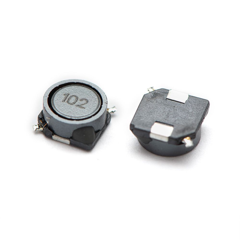
KUNYO TECH is the manufacturer of custom magnetic components. We have over 10 years of experience in the design and manufacture of custom wound transformer products and custom coil wound parts. We design and build a wide variety of custom magnetic transformers and coil components per specific customer requirements. All wound products are manufactured to the highest possible standards.
If you have a requirement for any specification of wound components and want to be sure your custom magnetic components are built to the correct specifications, our engineers are happy to discuss with you and provide you with engineering support . And we assist our customers throughout the entirety of the custom transformer design-build process. And we will provide you with the best possible custom magnetic components at the most reasonable price.

A component formed by winding a conductor into a coil shape with inductive properties is called an inductor. Inductance refers to the phenomenon where an alternating current passing through a conductor generates a varying magnetic flux inside and around the conductor. The inductance is defined as the ratio of the magnetic flux linkage to the current that produces it.
When a direct current (DC) flows through an inductor, the magnetic field lines around it remain constant and do not change over time. However, when an alternating current (AC) flows through the coil, the magnetic field lines around it vary with time.
In circuit diagrams, inductors are represented by the symbol L. The main parameter is inductance, measured in Henries (H). Commonly used units include millihenry (mH), microhenry (µH), and nanohenry (nH).
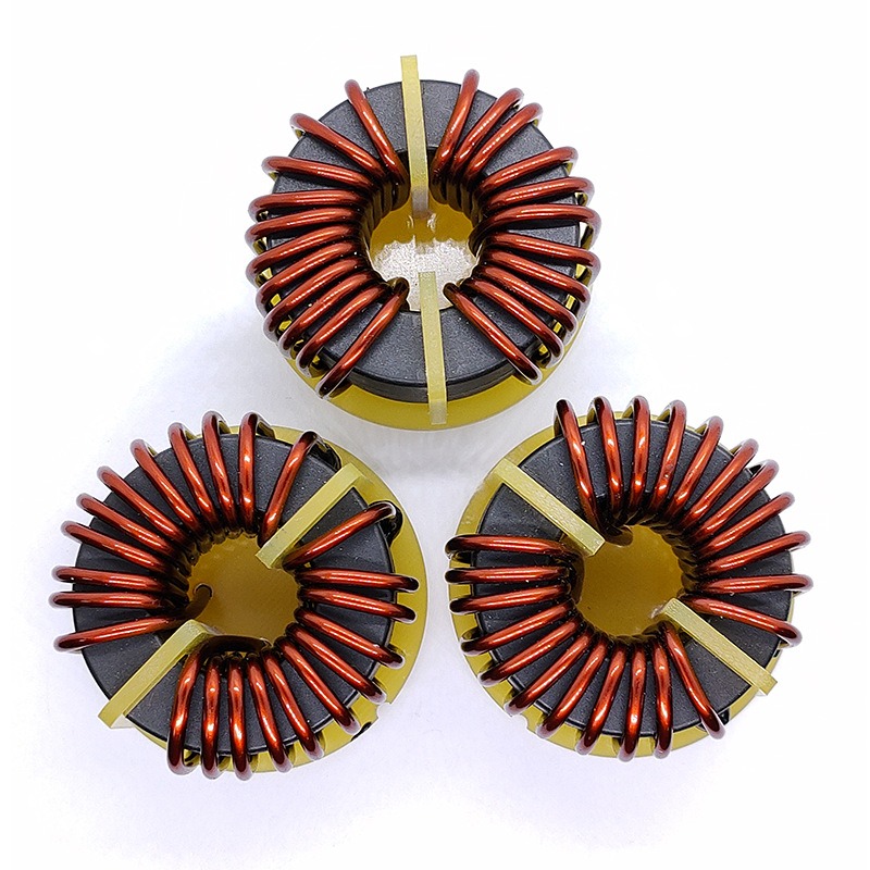
Inductor operates based on the principle of electromagnetic induction. When an electric current flows through a conductor, it generates an electromagnetic field around it. This electromagnetic field, in turn, induces an effect on the conductor itself as well as on other conductors within its range.
The effect that occurs on the conductor generating the electromagnetic field is called “self-induction,” while the effect on other conductors within the electromagnetic field is known as “mutual induction.”
The electrical characteristics of an inductor coil are opposite to those of a capacitor—it “blocks high frequencies and allows low frequencies to pass.” This means that when a high-frequency signal passes through an inductor coil, it encounters significant resistance, making it difficult to pass through. In contrast, low-frequency signals face much less resistance and can pass through more easily. The electrical resistance of an inductor coil to direct current (DC) is nearly zero.
Inductor coils are often simply referred to as “inductors” or “coils” and are represented by the letter “L.” The number of turns in a wound inductor coil is commonly called the “number of turns” of the coil.

The function of an inductor is to allow DC to pass while blocking AC, filtering (blocking high-frequency signals and allowing low-frequency signals), and boosting voltage.
The difference between a capacitor and an inductor is that a capacitor allows AC to pass while blocking DC.
The most common function of an inductor in a circuit is to work with a capacitor to form an LC filter circuit. We already know that a capacitor has the property of “blocking DC and allowing AC,” while an inductor has the property of “allowing DC and blocking AC.”
If a DC current containing many interference signals passes through a filter circuit (as shown in the diagram), the AC interference signals will be converted into heat and dissipated by the capacitor. The relatively purified DC current then passes through the inductor, where any remaining AC interference signals are converted into magnetic energy and heat. Higher frequency signals are more easily blocked by the inductor’s impedance, effectively suppressing high-frequency interference signals.

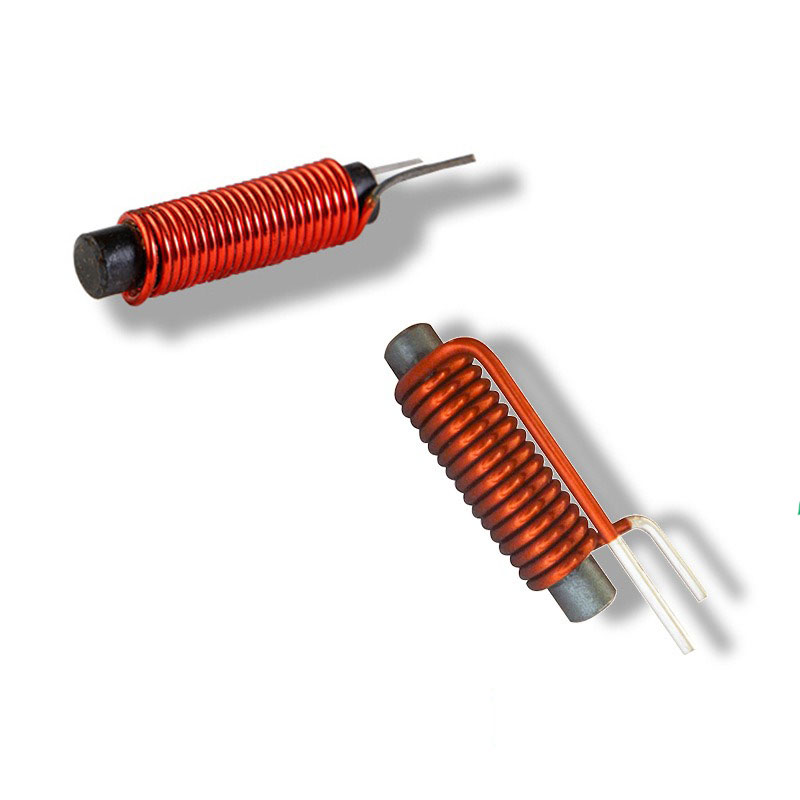
Inductor Coil: When an electric current flows through a conductor, a magnetic field is established around it. To enhance the magnetic field inside the coil, the conductor is usually wound into a coil shape. An inductor coil is made by winding a conductor (such as enameled wire, silk-covered wire, or bare wire) turn by turn (with insulation between each turn) around an insulating tube (which may be an insulator, iron core, or magnetic core). In general, an inductor coil consists of a single winding.
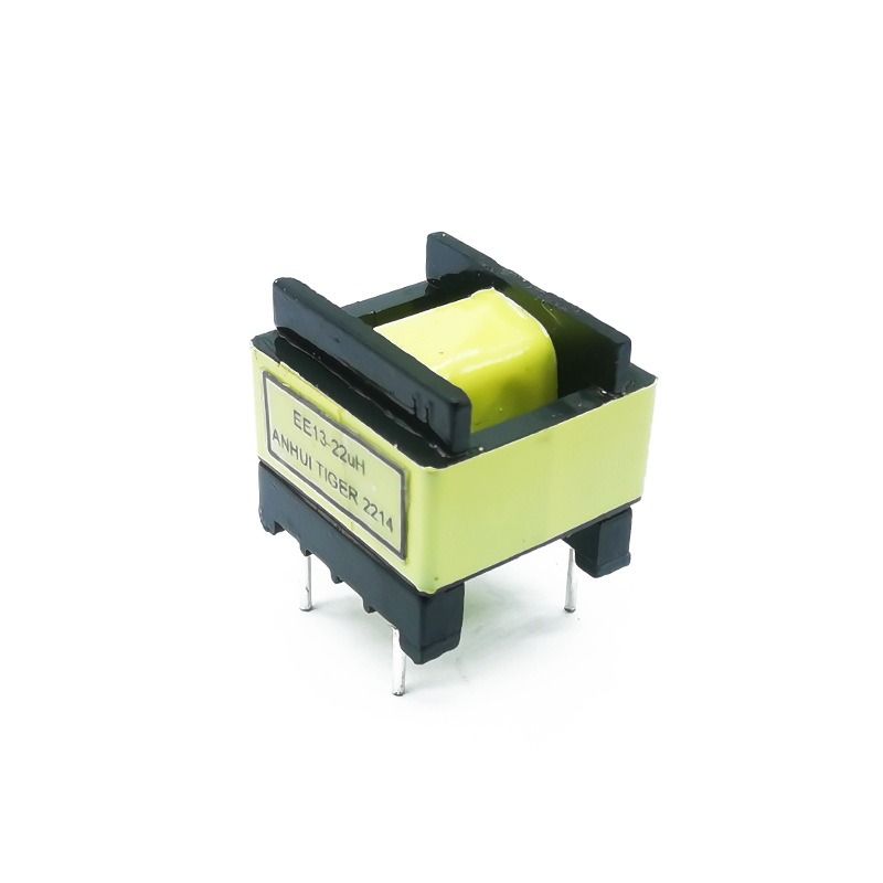
Transformer: When a varying current flows through an inductor coil, it not only generates an induced voltage across its own terminals but also induces a voltage in a nearby coil. This phenomenon is known as mutual induction. Two coils that are not electrically connected but are placed close enough to influence each other through electromagnetic induction are commonly referred to as a transformer.

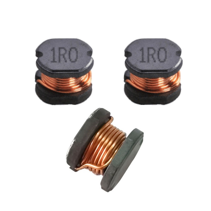
Once a PCB design is finalized, the packaging specification of the inductor is determined—whether it is a surface-mount or through-hole component, and whether there are EMI requirements. Some products require certification, meaning they must use shielded inductors to meet EMI standards.

Once the IC is selected, the required inductance value and current capacity become clear. In terms of current, the principle is that it is better to have a higher current rating than a lower one. If the current rating is too low, the inductor may saturate and overheat. A slightly higher current rating generally does not cause issues.
Next is the Q factor. Engineers often prefer inductors with a high Q value, as it indicates higher efficiency. However, excessively high Q values can lead to resonance effects, potentially damaging the inductor and capacitor. Therefore, Q values are typically required to stay within a specific range.
Lastly, frequency plays a crucial role in inductor performance. When making prototypes, it is essential to ask the customer about the product type and its operating frequency. The testing frequency should be close to or equal to the actual working frequency to ensure the most accurate test results.
• Cost Effective and High Reliability & High efficiency
• Design and build magnetic components per specific customer requirements.
• No MOQ purchase requirement or nonrecurring engineering (NRE) charge for custom parts
• Samples are for free
• Treat every request with the same care and commitment.


Established in 2013, Shenzhen Kunyo Technology is committed to designing and manufacturing custom magnetic components, including high-frequency transformers, low-frequency transformers, audio transformers, power transformers, and inductors.
You can get a price of this model or send us any question to get any information you would like to know, we will reply to you soonest.